
Building
Bryant Bannister Tree-Ring Building
The Laboratory of Tree-Ring Research had been in temporary accommodation under the west side of the Arizona Stadium for over 70 years, but has finally moved into a permanent home, the Bryant Bannister Tree-Ring Building. The building is named for a former director of the Lab, who (although retired) still manages to contribute to dendrochronological research. It has been made possible by a donation from Agnese Haury, widow of noted anthropologist Emil Haury, and already the donor of several generous gifts to the University of Arizona, including a training fellowship offered through the Tree-Ring Lab. A groundbreaking ceremony for the new building took place on May third, 2011, and preparations for the construction began in November; people and equipment moved in on January of 2013, and the building dedication was on March 1. The first phase of the building is a completely new structure adjacent to the present Math East building (where the Tree-Ring Lab had already occupied some space in the basement). A subsequent phase will move storage of the extensive collection of wood samples into the Math East building, once its present occupants can be accommodated elsewhere.
The architect has taken an innovative approach to accommodating extensive laboratory and office space on a small area of ground, while maintaining some visual associations to tree rings. The building itself is almost literally a tree house, with a block of offices and laboratories suspended high in the air at the roof level of the present Math East building, and screened by individually articulated metal tubes that resemble the leaves of the palo verde tree. The main trunk beneath this block contains public exhibition space and the multipurpose room that serves as both auditorium and teaching lab. The other supporting columns branch into diagonal supports in a way that evokes additional tree trunks.
The Math East south elevation before demolition or construction (Chris Baisan).
The Math East south-east corner before demolition or construction (Chris Baisan).
Construction site at the start of demolition (Chris Baisan).
Demolition of the overhang and loading dock (Chris Baisan).

Start of the excavation for the elevator shaft (Chris Baisan).

Basement concrete shuttering (Chris Baisan).

Basement concrete pour (Chris Baisan).
Basement waterproof coating (Chris Baisan).
Drilling column bases (Chris Baisan).
Steel arrival on site (Chris Baisan).
Steel, with the lower floors started (Chris Baisan).
Start of the 4th floor steel construction (Chris Baisan).
Steel for upper two floors on Math East roof (Chris Baisan).

North half of steel construction nearing completion (Chris Baisan).

Start of the south half of the steel construction (Chris Baisan).
Start of the south-east corner of the steel construction (Chris Baisan).
Steel construction viewed from the East (Chris Baisan).
Structural steel nearing completion (Chris Baisan).
Concrete poured for the 3rd floor (Chris Baisan).
External walls without panels or scrim (Chris Baisan).
View from the east, walls without panels (Chris Baisan).
Roof before completion of the screening enclosure (Chris Baisan).

The north-west corner without panels, windows, or scrim (Chris Baisan).
The temporary construction elevator on the north-east corner (Chris Baisan).
Positioning petrified wood to be embedded in the first floor concrete (Chris Baisan).

Pouring concrete for the first floor (Chris Baisan).

Concrete in the exhibit area (Chris Baisan).
Finishing pouring first floor concrete (Chris Baisan).
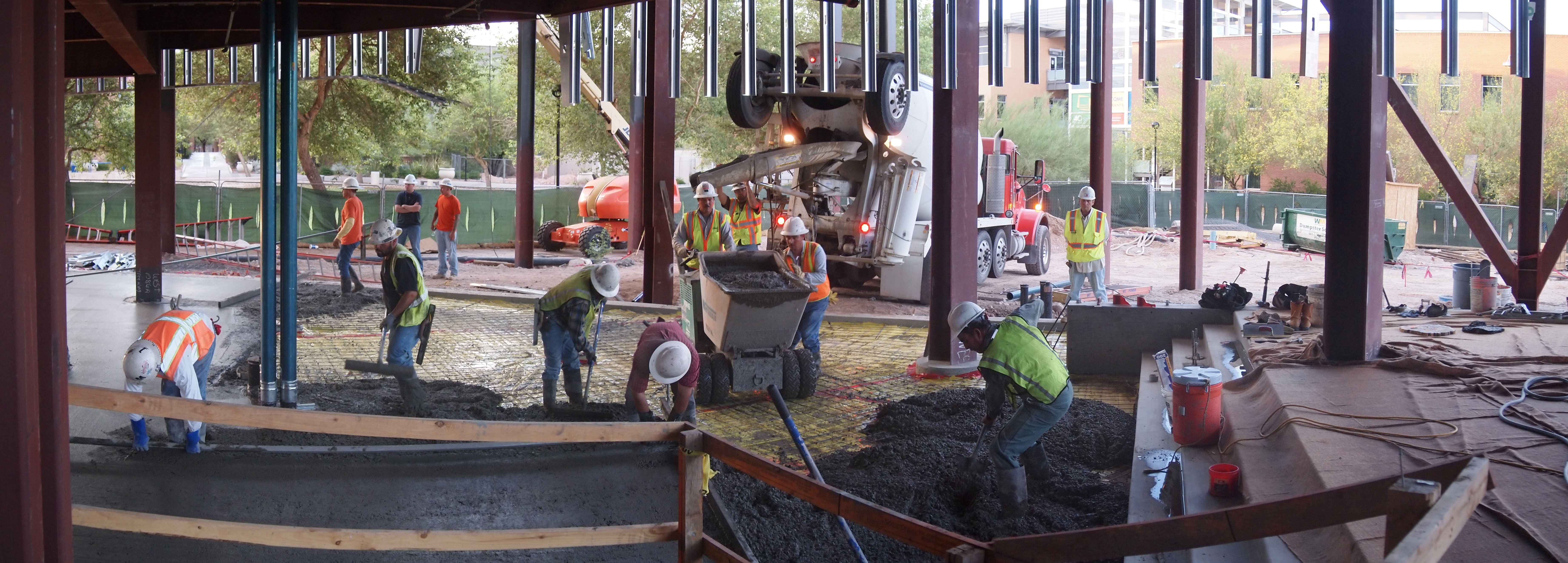
Concrete in the entrance area (Chris Baisan).

Starting hanging the scrim on the south elevation (Chris Baisan).

Starting hanging the scrim on the west elevation (Chris Baisan).
The following small images of the new building are links to full-sized printable documents with additional annotation.

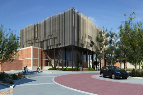
Perspective view looking south-west (Richärd & Bauer Architecture).
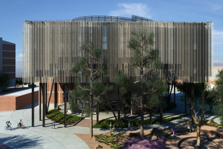
Perspective view looking north-east (Richärd & Bauer Architecture).
Perspective view looking north (Richärd & Bauer Architecture).
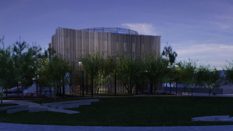
Perspective view looking west at dusk (Richärd & Bauer Architecture).
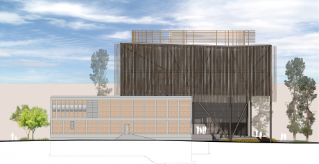
Elevation — West (Richärd & Bauer Architecture).
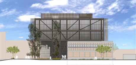
Elevation — North (Richärd & Bauer Architecture).
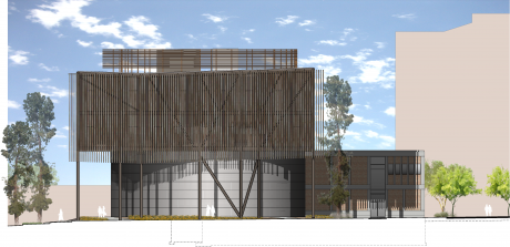
Elevation — East (Richärd & Bauer Architecture).
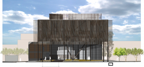
Elevation — South (Richärd & Bauer Architecture).
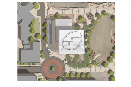
Plan — site (Richärd & Bauer Architecture).
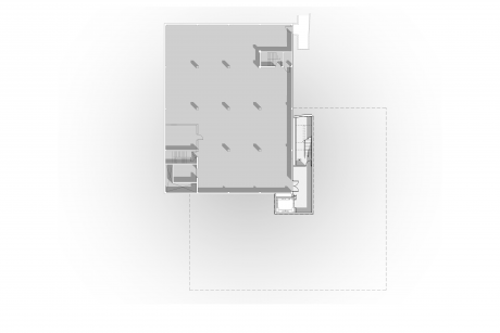
Floor Plan — Basement (Richärd & Bauer Architecture).
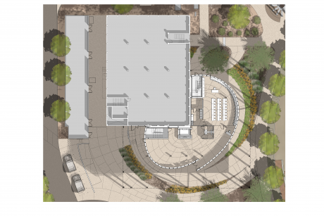
Floor Plan — 1st Floor (Richärd & Bauer Architecture).
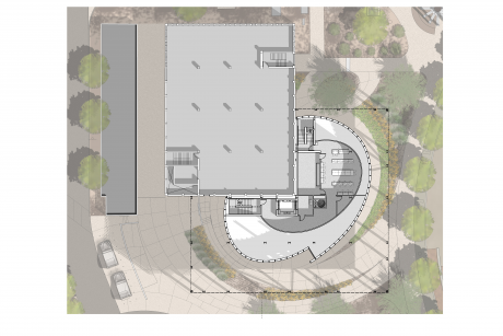
Floor Plan — 2nd Floor (Richärd & Bauer Architecture).
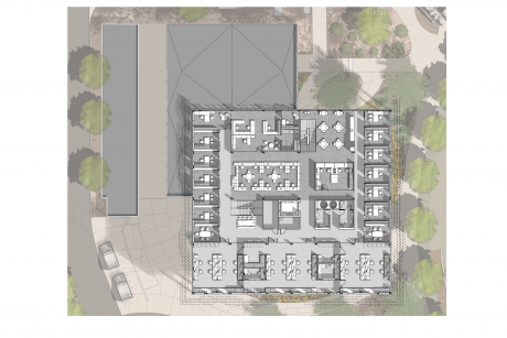
Floor Plan — 3rd Floor (Richärd & Bauer Architecture).
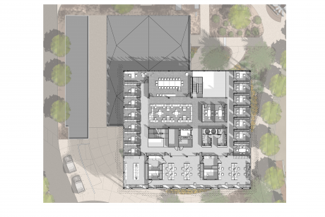
Floor Plan — 4th Floor (Richärd & Bauer Architecture).
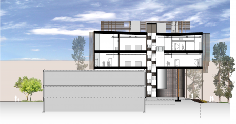
Section — looking East (Richärd & Bauer Architecture).
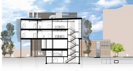
Section — looking West (Richärd & Bauer Architecture).